Posts

Showing posts with the label Tinius Olsen

Revolutionising the World of Plasma and Corona Surface Treatment Systems
Image
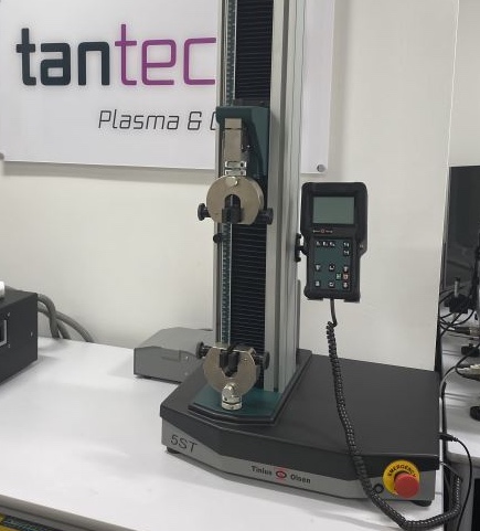
Tantec UK & Ireland manufacture Plasma and Corona Surface Treatment Systems, which improve the surface of materials, especially non-stick polymers like polypropylene, so that they can be adhered to when bonding, printing and coating. The company has a rich history supplying some of the world’s leading manufacturers since 1974, producing plasma and corona surface treatment systems for cutting-edge industries including aerospace, automotive and medical. Their products play a critical role in everyday life. Revolutionising the world of surface treatments by inventing plasma and corona systems for 3D components, Tantec have continued to operate at the forefront of the sector, being one of the few organisations worldwide specialising in both technologies.   “For almost half a century we were developing thousands of surface treatment solutions and we continue to work closely with a broad range of industry sectors, supplying standard and bespoke systems to meet their requirements,” says M

How Molasses Helped Shape the Modern World of Construction Regulations and Materials Testing

Image
Major incidents and disasters down the years have helped shape the modern world of materials and structural testing to recognised International Standards. One such example happened in Boston over 100 years ago……………….   There have been many accidents and disasters over the years that could, and should, have been averted by effective materials testing. Indeed, on more than one occasion, with any materials testing at all! One such incident was the Great Molasses Flood, also known as the Boston Molasses Disaster, which occurred on January 15, 1919 in the North End neighborhood of Boston, Massachusetts.  The tank at 529 Commercial Street before the disaster A large storage tank filled with 2.3 million US galloons, weighing approximately 13,000 short tons, of molasses burst and the resultant wave of molasses rushed through the streets at an estimated 35 mph (56 km/h). The event entered local folklore and residents claimed for decades afterwards that the area still smelled of molasses on hot

From Superheroes to Super Science………

Image
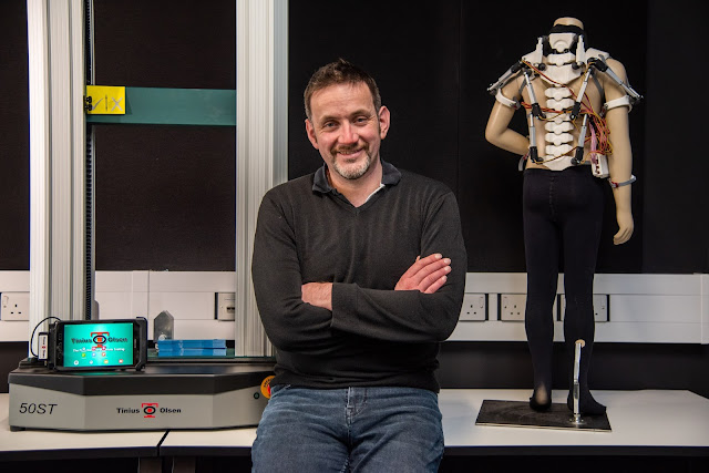
Robotic exoskeleton technology has been with us for almost sixty years but the most recent advances in its composites base could see it being an integral part of missions to Mars in the 2030’s. A more detailed technical analysis of the composites engineering utilised in the development of the exoskeleton can be found by listening to an Inform webinar, produced via IOM3, via  https://vimeo.com/563847105/6cdf28dbdf To many of us the term exoskeleton is reserved for the realms of science fiction or conjures up images of body armour clad superheroes such as Iron Man or even Batman. Although the vast majority of these have sprung from the fertile imaginations  of artists and writers, the equally fertile lobes within the scientific community are turning this science fiction into science fact. An exoskeleton is a rigid structure that wraps around the body and is often used to assist joint movement. This ‘exosuit’ try ’ s to act like an artificial muscle, aiding the wearers’  muscles to contra

S274 - Mesh Weld Shear Test

Image
This attachment is used to test the strength of the welds that hold mesh together. The mesh is often used as a reinforcement for concrete structures. as this is a structural component it is essential to test the consistency of the weld in any given section. A joint is cut from the mesh and placed in this attachment. A grip, the HW 14 is then placed on the end of the rod. a force of up to 50 kN is then applied and the shear strength of the weld measured. There is some adjustment in the design with a sliding plate that allows for different gauges of wire. The applicable standards are: BS4483, ASTM A185, ASTM A497 and ASTM A974. The testing application note for this grip is available from the resource area of our School of testing microsite or by clicking here .

S0991 Carton Bend Test

Image
This a ttachment , the S0991 is designed to test how card and paper folds, a small sample section is taken and placed under a retaining bar, this is then forced to fold using the fold bar at the back. A rotary digital encoder measures the rotation angle and compares it to the force measured on the loadcell . To ensure self-alignment cord is used to rotate the pulleys that move the folding bar. Used in the packaging industry this compares how easy is is to open your box of cereal in the morning and to see how strong the folds are...

106-001 - Self-Aligining Fixture

Image
It's sometimes necessary to attach a grip or fitting that has no way of self aligning , in these cases we've developed several ingenious ways to add this function to the machines. One of these methods is to use a Self- Aligning Fixture like the one shown in the picture. As it is designed to fit a 150 kN U-Series machine it is somewhat massive. The top thread being 1" UNF in diameter and the bottom an M33. It weighs, a not insignificant , 7kg; has a 110mm body diameter and is nearly a foot tall. The central pin that you can see has is supported by a Nitrile block which allows it to float, whilst absorbing the shock of a sample failure.

276-003 Compression Platens - With Guide

Image
The Compression of a spring can be quite a hard thing to measure, the spring has a tendency to want to exert it's applied force horizontally to the platens (in other words, fly off under the nearest table...) This isn't really a problem, just a nuisance and in some applications a desirable feature of springs... To stop the test sample from flying off these compression platens have a free running guide that retracts into the top body. This holds onto the spring, whilst having a known affect on the test.

760-001 - ASTM D429-03 - Double Shear Adhesion Jig

Image
The ASTM D429-03 69.1 (Method G) is for testing the adhesion properties of rubber. The rubber is pre-formed onto 3 metal plugs. this gives a double rubber sandwich that can then be tested. This attachment holds the metal components of the sandwich and allows a double shear test to be performed.

123-001 - 250mm Textile Grip

Image
A range of faces make the 123-001 Textile Grip an adaptable and very useful attachment. Textiles can be a very hard materials to test, they can be very strong in tension, and unless ripped, near impossible to break… it can hold large amounts of energy and can break with a bang! The grips that hold fabric tend to be hydraulic and have special grip arrangements because of this property. There are 3 types of face of the jaws. Plain, Hatched and Grab each have a specific set of materials that they can be used with, each with singular benefits. The 123-001 holds the sample between two 250mm wide faces, these come together with a clamping force and the test can then be performed. If you're interested in this or other Textile testing, please contact Sylvia Hillier or go here: http://www.testingtextiles.com/

276-001 - Self Aligning Platens

Image
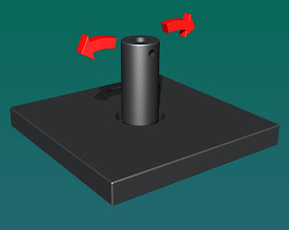
As mentioned before, we do a wide range of platens (two parallel plates that are used to compress the test specimen...) Often the sample is uneven or has protruding features, the fixed platens are less effectual in this instance. In cases like this, self aligning platens distribute the load across the sample by increasing the contact area. (The arrows show movement...)

160-001 - ASTM D5801-95 - Bitumionous Material Test

Image
It's really nice to be able to show you some pictures of the finished products, rather than renderings. The attachments, once checked, go straight to the customer... (so we don't often get time for pictures). This test is for Bituminous Materials, like tar -or- polymer modified asphalt (depending on you professional inclinations). The ASTM Standard calls for a very precise procedure that includes warming and filling a 3oz. pot with the sample and lowering a semi-sphere into it. This is then extracted and the forces required measured... It's quite a demanding test for the equipment as the sample material is quite, well, sticky... so we've made the parts that would come in contact with the sample out of stainless steel, this should allow the parts to be cleaned without having to worry about affecting any surface finish.

Wood Fixings - Tinius Olsen - BS EN 1382:1999 Fixture

Image
This attachment simply pulls nails and staples from wood, as you could imagine it is very important to know and understand the way in which fixings behave in wood. As wood is a natural substance each plank is different from the next, and it is the job of BS EN 1382:1999 to ensure that fixings (nails and staples in this case) that are a known quantity behave the same way in different kinds of wood (nails and staples are produced on mass and so are quantifiable). There are two attachments, one for nails and one for staples. It can hold a variety of nails and staples due to the taper on the attachments. The lower component holds the wood, it is common with ASTM D1037 & D1761 Standards which are similar wood tests.

Sometimes we all need a little more...

We've been thinking, there are lots of great resources and information regarding testing machines and attachments, but we don't want to put them all on here. It might get a little cluttered... Our colleagues at Tinius Olsen have put together a good list of resources on the Tinius Olsen Homepage. The direct link to the list can be found here

Tinius Olsen - ASTM D2519-02 Electrical Insulating Varnish

Image
830-001 ASTM D2519-02 Electrical Insulating Varnish The ASTM standards (sometimes) give accurate and very precise instructions on how a specific test should be performed. This is an example of one of these tests, the parts and method are explicitly layed out within the standard document. This attachment uses a 3 point bend applied to a coil to test the strength of Electrical Insulating Varnish. The coil, made from various metals, are wrapped tightly around an anvil. The anvil is then removed and the coil placed in the varnish solution. The coated coil is then placed in this 3-point bend and then tested. This is then used to show the properties of the varnish when applied to the metal. As this test uses the appropriate materials in an accurate situation it should produce good results.

S0997 - Tinius Olsen - Smart Card Push Out Test

Image
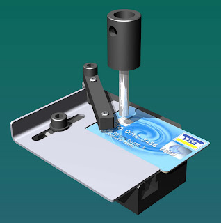
W e often come across the problem of testing the strength of fixing methods like adhesives. But how do you test the finished product once the product is produced? Increasingly credit and debit cards have small microchips on them. These are generically called 'Smart Cards' as they contain a great deal of information on the 'chip. To test the strength of these cards, in particular the bonding strength, this attachment has been developed. It is adjustable so that the 'chip can be tested wherever it is placed on the card. There is a retaining arm that is used to hold the card in place, this has a roller on the bottom that allows quick changes. There is a specific routine that allows the chip to be pushed through and the force required is measured...

Right tool for the Job...

Image
We sometimes need a little help to get things off the ground... For safetys sake, it's worth hiring the correct equipment to move Tinius Olsen machines around. This is one of our machines being moved into our Demo Suite, which happens to be upstairs!

S0995 - Tinius Olsen - ISO 594 Female Luer Fitting

Image
A Luer fitting is the common name for a tapered fitting that adheres to ISO 594. In this case it was necessary to hold a needle which had a Luer attachment on it. this was to be used for puncture testing, so no thread was required. Used as in conjunction with S0994, this test used a range of standard needles with Luer ends. This simple needle or luer attachment could be used for any number of compression, puncture tests on components with Luer ends.

S0994 - Tinius Olsen - BS7320 Specification for sharps containers

Image
This Grip is used to test the bodies of Sharps Containers. As you might imagine, it is very important that 'sharps' cannot penetrate the sides of the container. This grip is used to hold a fine needle in one end, and a sample of the moulded box the other. There is a piece of foil underneath the specimen , this allows the system to know when the needle has punctured right through. An accurate measurement of the force required is then taken. The needle holder rotates allowing the user to insert the needle without bending over or risking hurting themselves with the needle. The base is a simple stand with hole, the connection to the foil is made with a clip.

S0453 - Tinius Olsen - 100kn Seat Belt Grip

Image
These grips are used to test seat belts and webbing up to 100mm thick. seat belts have interesting properties, they have to cushion the shock of a crash without injuring the passenger of the car at low speed stops. In a collision it has a precise elastic limit, meaning that it stretching slightly to diffuse the shock, goes beyond its elastic limit, becomes plastic then holding it's passenger without breaking, there is a great deal of force involved in this process (which is why these grips are rated to 100 kN ...) The testing can be quite explosive as the belt stores a great deal of energy before failing. By exerting a tensile force on the belt it is possible to see how it will behave. One of the important features of this grip is that it is self tightening. The specimen is feed through the grips in a specific manner as not to damage the belt. A damaged belt can dramatically affect its ability to protect the passenger, and once it has been stretched to it's elastic limit and

S0969 - Tinius Olsen - Astm D143 Wood Tension Parallel to Grain

Image
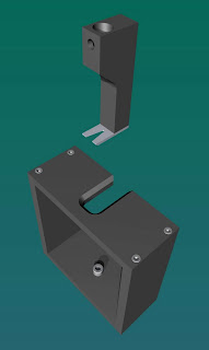
This grip is designed to meet the very strict guidelines set within the ASTM D143 standard. I have mentioned this standard before, it is one of the most demanding standards available for wood specimens. One of the most important tests when it comes to the structure of wood is how it reacts in tension. As wood can be very strong in tension it's is necessary to 'profile' the sample (cut the wood into a specific shape) so that the region undergoing test is uniform, in the middle and weaker than the grip or piece of wood the grip is holding onto. It also needs to be smaller to allow an extensometer to be added to measure the small changes in the length of the sample. This grip is essentially self-aligning, the sample slotting into the two fingers.